

How Contacts Connect and Interrupt Current Flow
Key Summary
- Basic structure of an electrical contact system — the role and operating principle of the Movable Contact and the Fixed Contact
- The two representative contact form types — structural differences and application points of the Rivet Type and the Tip / Plate Type
- Contact resistance, contact bounce, welding, and other switching phenomena, and how material/design address them
In our August blog, we covered the properties of electrical contact materials, where they are used, and the importance of choosing the right Contact Material. In September, we take it one step further: this post explains the actual structure of a contact — the Contact System — and how it connects and interrupts current. Date: 2026.09.18 — Contact System from the Perspective of Movable and Fixed Contacts
How a Contact Operates
Movable Contact and Fixed Contact
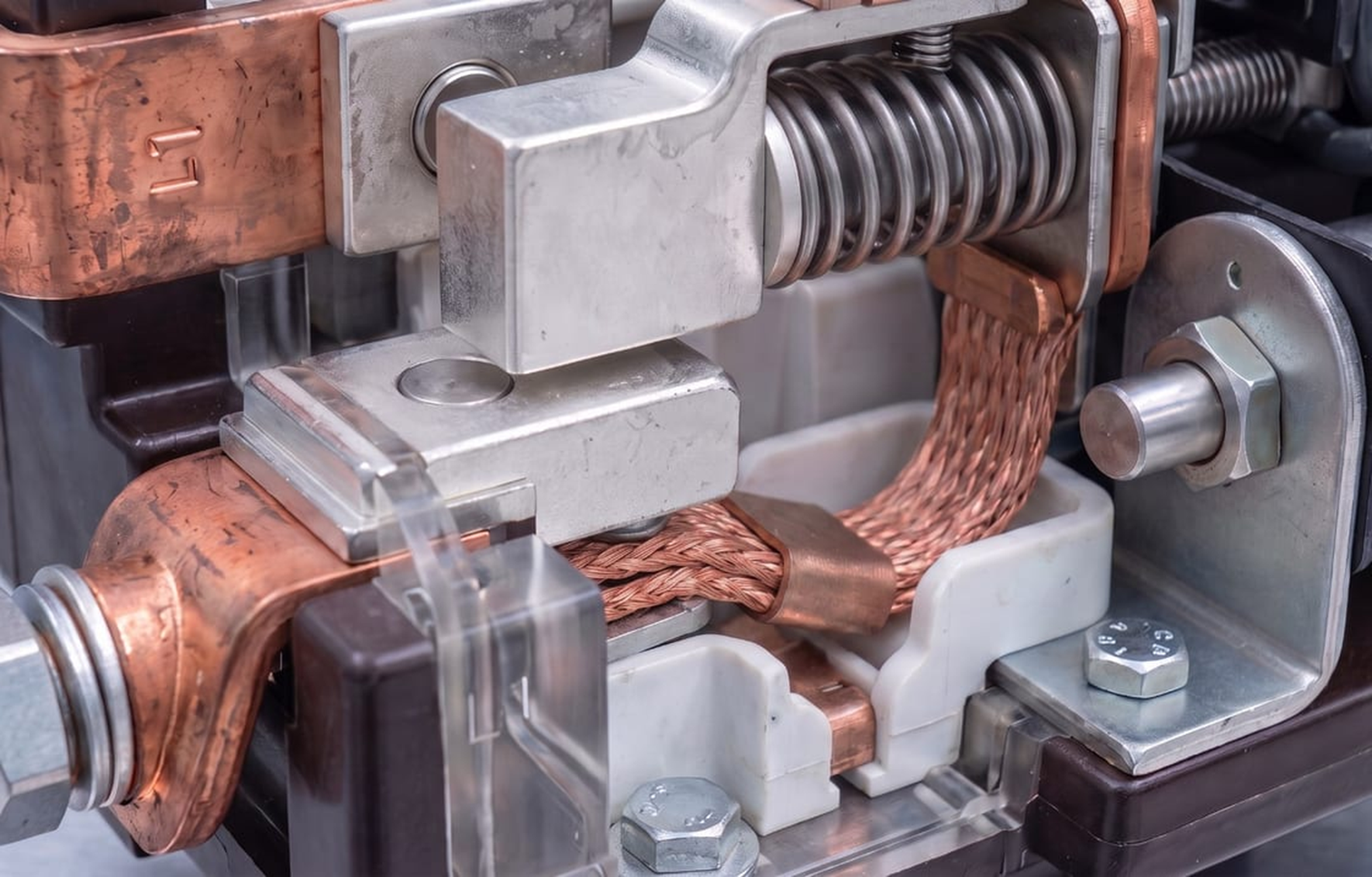
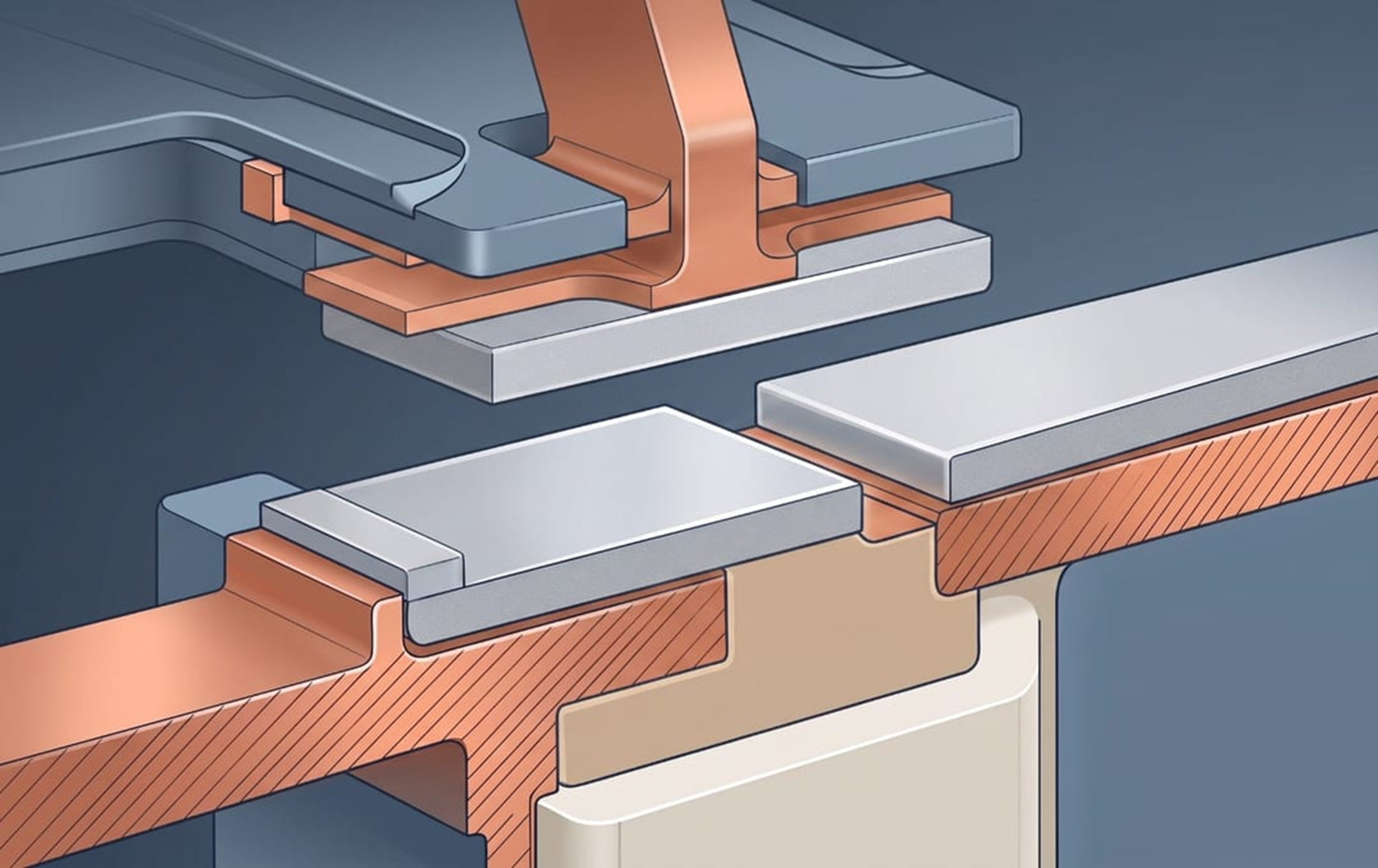
An electrical contact system is composed of a Movable Contact that moves and a Fixed Contact that stays stationary. The Fixed Contact is mounted in the housing or a support and serves as the reference point for the current path, while the Movable Contact is connected to a drive element such as a coil and armature and moves to open and close the circuit. When the relay operates, the Movable Contact shifts into contact with the Fixed Contact (make) or separates from it (break). Contact forms (Form A, Form B, Form C, etc.) are also expressed as the combination relationship between the Movable Contact and the Fixed Contact. In short, the operating reliability of a contact is determined not only by the material properties but also by system-design factors such as the structure of the moving part, the contact force, and the contact gap.
Contact Form
Rivet Type
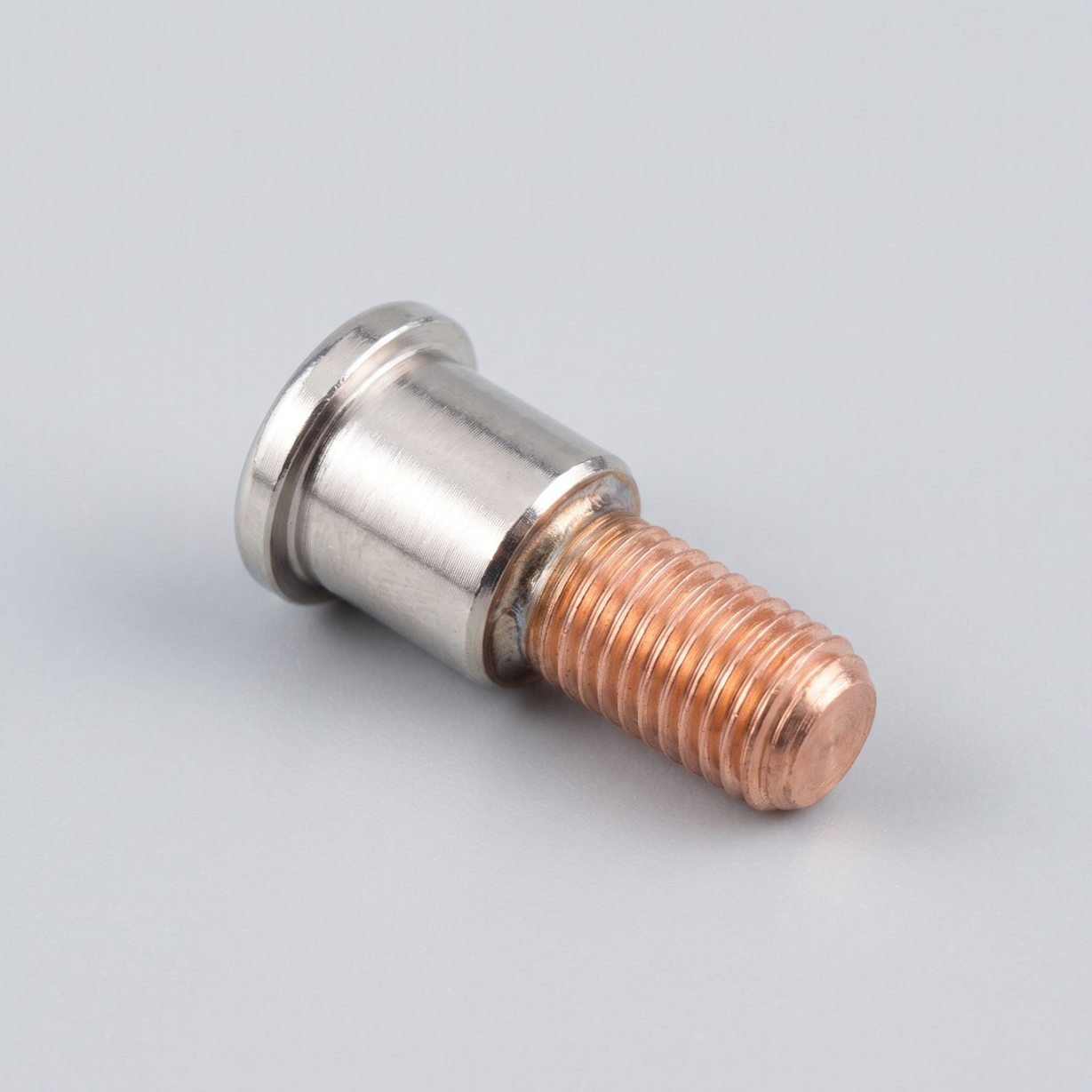
A Rivet-Type contact is made up of two parts: a Head that performs the actual contacting, and a Shank that is riveted into a substrate or bracket.
A representative example is the Bimetal rivet —the head uses a silver-based contact material, while the shank uses copper or a copper alloy.
This reduces silver usage while securing both conductivity and joint strength.
Because riveting is a simple joining process, rivet-type contacts are widely used in low- to mid-current products such as small Relays and Switches, and the structure is well suited to mass production.
Our Contact Wire is processed into Contact Rivets of this type through downstream operations.
Tip / Plate Type
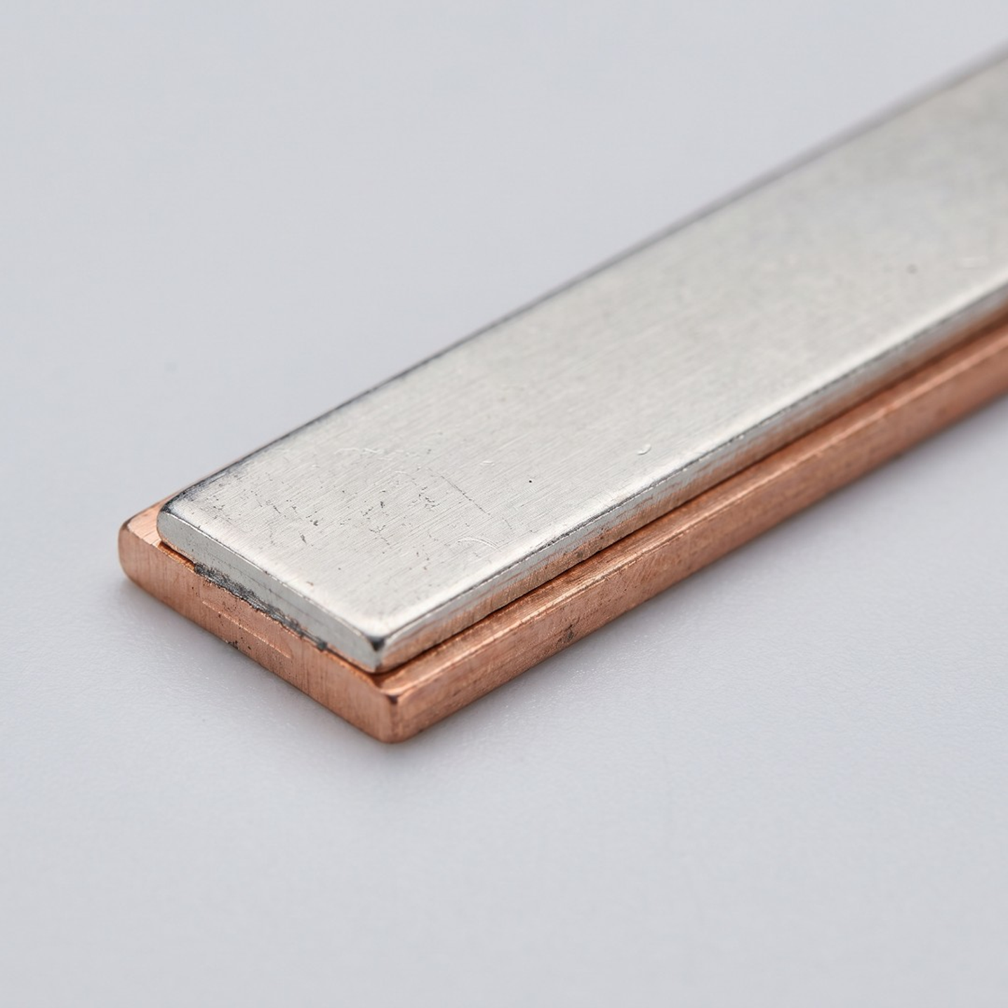
A Tip / Plate-Type contact has a broad, flat contacting surface and is mounted to the joining surface by brazing (hard-solder joining) or welding.
The larger contact area distributes contact resistance over a wider region and leaves more material margin against arc erosion, which makes the form well suited to high-current power devices such as Contactors and Circuit Breakers. Our Contact Tip is a representative plate-type product, manufactured in various shapes and dimensions according to product structure and joining method.
With the Movable Contact and Fixed Contact facing each other surface-to-surface, this geometry delivers stable current conduction in high-current environments.
Contact Resistance
Contact Resistance
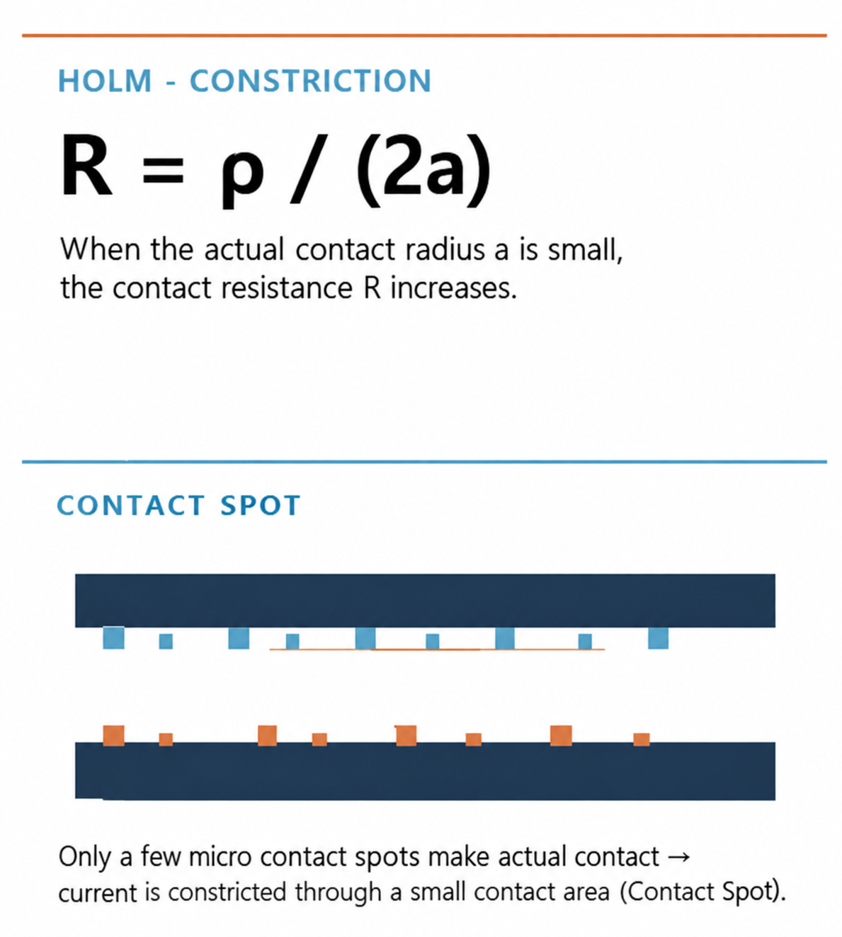
Even though a contact surface looks flat to the naked eye, only microscopic asperities actually touch each other at the micro scale.
The actual current passes through a small number of these contact spots and constricts (Constriction).
In Holm’s contact theory, the constriction resistance of a single circular contact spot is expressed as R = ρ / (2a).
The smaller the actual contact area, the higher the contact resistance. A higher contact resistance means greater I²R heating, which raises the contact temperature and increases the risk of material degradation and welding.
Surface films and contaminants also raise contact resistance, so material selection must be considered together with contact-force and geometry design.
Phenomena that occur during switching
Bounce and Welding
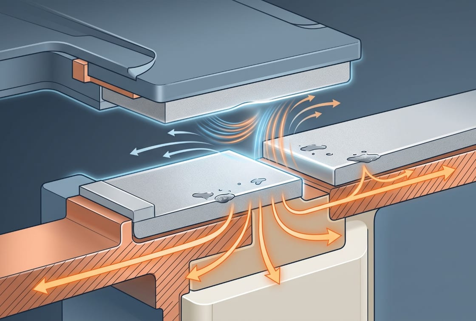
Contact Bounce is the phenomenon in which, at the instant of closing, the contact momentarily opens and recloses micro-mechanically under rebound forces rather than settling cleanly.
When bounce occurs, arcs repeat in rapid succession and accelerate surface erosion of the contact.
In particular, when a bounce is followed by a reclose, localized heating can easily cause Dynamic Welding — the two contacts sticking together.
Welding can occur not only when the contact is closed but also in a reclose situation immediately after a break.
Selecting a material with strong welding resistance — such as the AgSnO₂ family — is the key response to these phenomena.
System-Level Contact Design
Design points by load condition
For loads with high inrush currents — such as LED power supplies, SMPS, capacitor-input circuits, and motors — the ability to withstand the instantaneous peak current is critical, and the AgSnO₂ family is advantageous.
For products that switch repeatedly at small size and high frequency, the AgNi family offers a good balance of wear resistance and cost efficiency.
We propose geometries and dimensions for the Movable Contact and Fixed Contact in our customers’ products through Silver-Alloy-based materials (AgNi, AgSnO₂, AgZnO) and product groups — Contact Wire, Contact Rivet, Contact Tip.
Material selection must be reviewed in combination with system conditions including contact form (Rivet/Plate), joining method (Riveting/Brazing/Welding), contact force, and contact gap.
FAQ
Q1. Can different materials be applied to the Movable Contact and the Fixed Contact?
Yes. Asymmetric combinations are sometimes used — for example, a welding-resistance-oriented material on one side and a wear-resistance-oriented material on the other — to tune material transfer and welding characteristics. However, the combination performance must be validated under actual switching conditions.
Q2. What is the selection criterion between Rivet Type and Plate Type contacts?
It is decided by combining current rating, joining method, space constraints, and production method (Riveting / Brazing / Welding). As a rule, Rivet Type is widely used for small Relays, and Plate Type (Tip) for high-current Contactors and Circuit Breakers.
Q3. How can contact resistance be reduced?
Real (actual) contact area must be secured through contact force and geometry design, surface condition must be managed, and the contact-zone material and microstructure must be properly engineered. A material with more stable contact-zone behavior can be more advantageous than a material with simply higher silver content.
Q4. If welding occurs frequently, is changing the material enough?
Material change is one response. However, a fundamental response requires jointly reviewing system factors such as contact-bounce behavior, contact force, opening speed, and the inrush conditions of the load.
Q5. How is the geometry of the Movable Contact and Fixed Contact decided?
It is determined by product structure, joining method, required physical properties, and manufacturability. The downstream-processing conditions — from Contact Wire to Contact Rivet or Contact Tip — must also be considered.